"Updated February 18th, 2009"
|
Please note that all of the small pictures shown in this article are
backed up by larger images so that you can get a better look at the
details if you so desire. Just click on any of the small pictures to
look at the larger version. When done looking at the larger picture,
just hit the "Back" button on your browser to return to the main article.
Building this project requires the use of tools that are capable of serious injury to you. If you attempt to build this project or something similar be sure you wear safety glasses and use all necessary safety precautions. If you are not familiar with the use of the tools required, obtain assistance from someone who is familiar with their proper use.
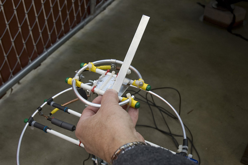
Project Goal
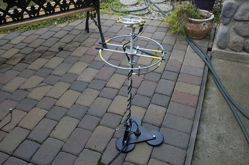
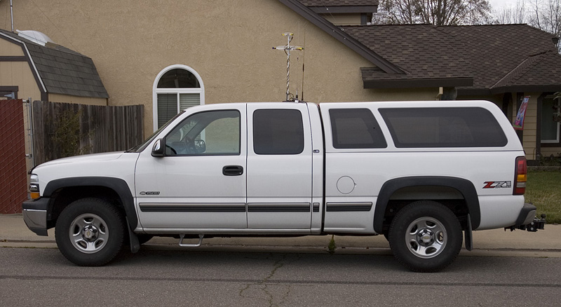
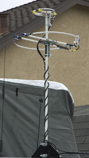
When starting the project I knew it was going to take some experimentation and some effort to work through the design and eventual problems that would crop up. For that reason I decided to take my time and work though the issues and tuning at a leisurely pace. This would allow time to experiment and try different things to get it right. Even at this point with the antenna system working and in a fairly robust state there are still parts of the design that need improvement. Since taking the picture to the right I have improved a couple of items that may not be noticed at first glance. I will explain in more detail later in this article.
Material Selection
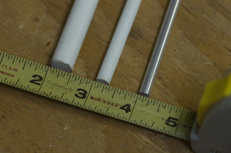
The next question was what to use for the mast and loop support? I found
some pieces of fiberglass tubing that I had from an old camping tent that
had since been discarded. The fiberglass tubing was about 5/16" in diameter.
I figured the fiberglass tubing would make a pretty good selection for the loop
cross brace. It could also be used as a temporary mast for the debug stage
of the antenna build.
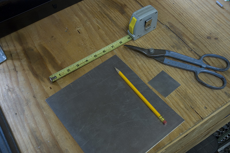
For the 2 meter gamma match connector I used 1/4" aluminum bar stock. For the 70 centimeter gamma tube connector I used .030" aluminum sheet material. The aluminum sheet material was also used for the ground point connectors on both antennas.
Tools
Fabrication (Bending the loop) 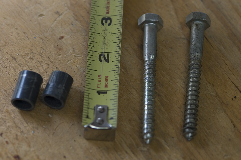 The first thing I wanted to do was to bend the antenna element. I knew that the
aluminum rod that I had selected would be more difficult to bend into the correct
shape than the soft copper tube I had previously used for my base antennas.
The first thing I wanted to do was to bend the antenna element. I knew that the
aluminum rod that I had selected would be more difficult to bend into the correct
shape than the soft copper tube I had previously used for my base antennas.
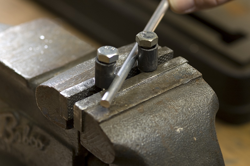
 For that reason I needed a method to bend the rod other than just using my hands.
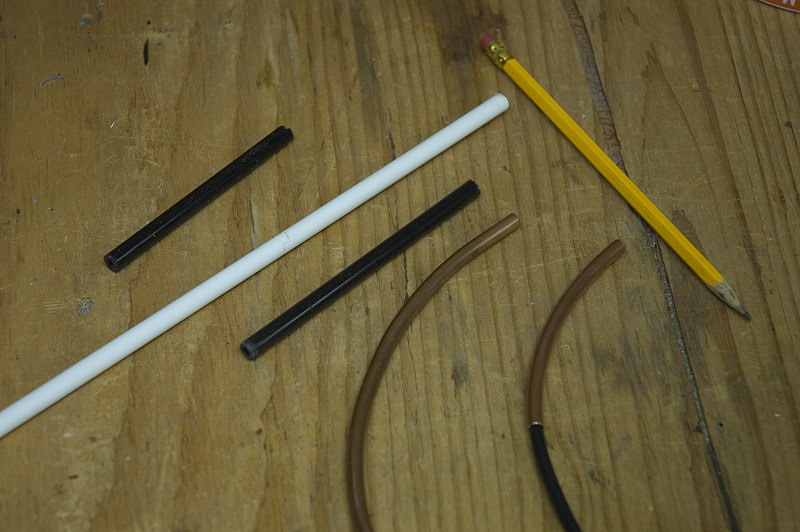
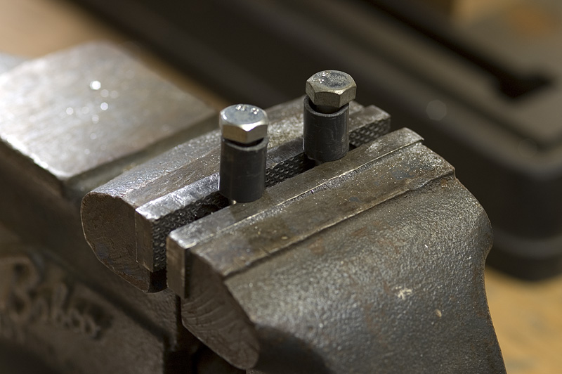
I found a couple of lag bolts and cut a couple pieces of plastic tube to use as a
bending tool. I used the bolts to bend the aluminum rod once they were
clamped into a vice. The two pieces of plastic tube were used to allow the aluminum
rod to slide easier past the bolts as I bent it. Once the two lengths of plastic
tube were cut, they were installed on the bolts as can be seen in the picture to
the right.
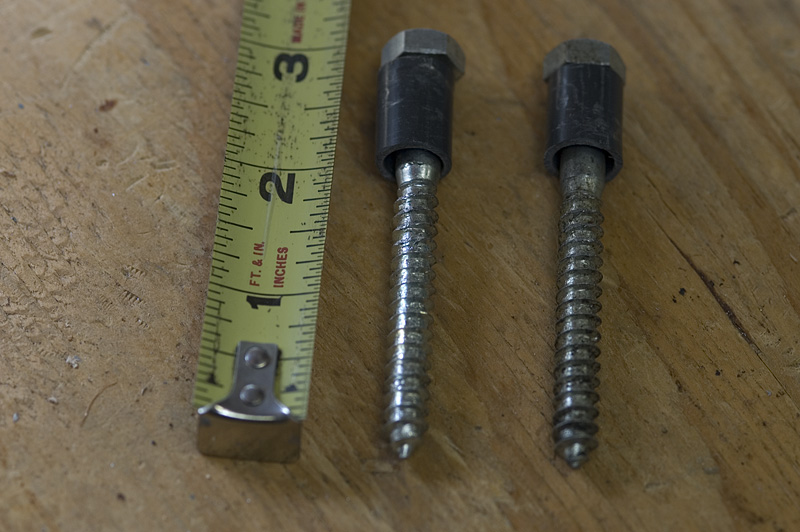
For that reason I needed a method to bend the rod other than just using my hands.
I found a couple of lag bolts and cut a couple pieces of plastic tube to use as a
bending tool. I used the bolts to bend the aluminum rod once they were
clamped into a vice. The two pieces of plastic tube were used to allow the aluminum
rod to slide easier past the bolts as I bent it. Once the two lengths of plastic
tube were cut, they were installed on the bolts as can be seen in the picture to
the right.
Before bending the aluminum rod for the antenna radiating element I cut it to the correct length. I then marked the center point for later connection to the ground clamp. Marking the center point before bending the rod into a circle is much easier than trying to do it after the rod is bent. I calculated the length of the element by calculating what the length should be at 1/2 wave length at 144.250MHz. I don't use the formulas normally found in books because I tend to forget the exact number. I just calculate it using the speed of light as a starting point. The speed of light is approximately 186000 miles per second in free space. 186000 miles per second is not exact but it is close enough for our purposes. First I convert 186000 miles to a number that will mean something to me. So I convert the distance to feet. There are 5280 feet per mile so (186000 miles X 5280 feet = 982080000 feet). We now need to divide the number of feet traveled in one second by the target frequency (982080000/144250000 = 6.8 feet). Then convert 6.8 feet to inches (6.8 feet X 12 inches = 81.6 inches). 81.6 inches is how long one wave length is at 144.250MHz. Since the propagation velocity of the signal traveling through the element is somewhat less than the speed of light through free space I used 98% as a multiplying factor. So (81.6" X .98 = 79.97"). I just rounded 79.97" off to 80". The loop is 1/2 wave length so I divided 80"/ 2 to arrive at 40" for the final length of the copper radiating element. This value is still a little longer than what will actually be needed. This allows for final antanna adjustment once everything is built.
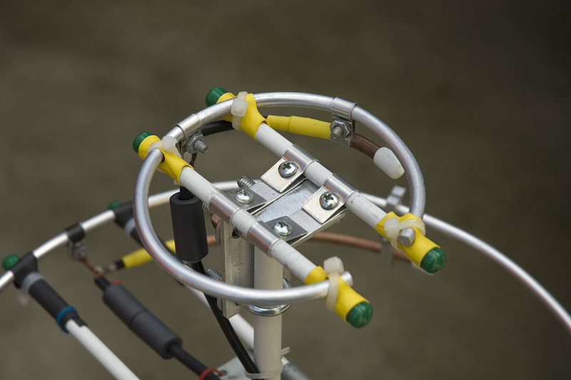
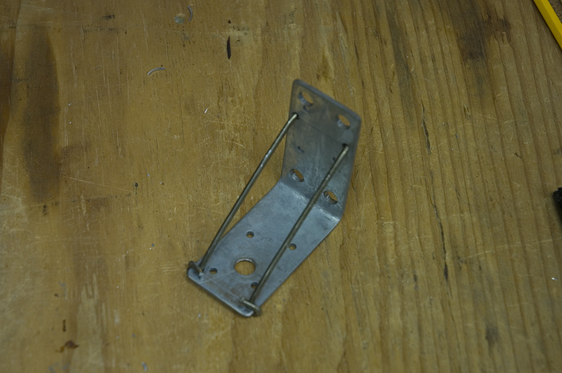
(Mast bracket for 2 meter loop) 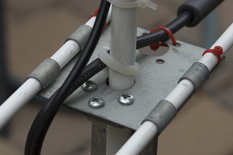 Once the loop was bent into shape I cut two lengths of fiberglass rod to use as
a connector between the radiating element and the mast bracket. I also had to
make the mast bracket so that it could connect to the fiberglass rods. I made
the attachment bracket out of two different pieces of metal. The first piece
was the piece that held the fiberglass cross brace rods. I made this piece out
of a discarded computer hardware bracket that I was able to cut up and bend
into the shape needed. This piece of the bracket assembly can be seen in the
picture on the left.
Once the loop was bent into shape I cut two lengths of fiberglass rod to use as
a connector between the radiating element and the mast bracket. I also had to
make the mast bracket so that it could connect to the fiberglass rods. I made
the attachment bracket out of two different pieces of metal. The first piece
was the piece that held the fiberglass cross brace rods. I made this piece out
of a discarded computer hardware bracket that I was able to cut up and bend
into the shape needed. This piece of the bracket assembly can be seen in the
picture on the left.
(Attaching the loop to the support rods) 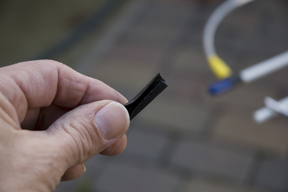
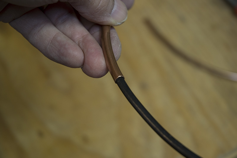
 Next was how to attach the aluminum loop to the fiberglass cross rods. I ended up
using a piece of coax insulation that was split and then wrapped around the
aluminum rod and then attached to the fiberglass cross supports using plastic ties.
A picture of a piece of the split coax insulation material is shown in the picture
to the left. The picture on the right side shows how the coax insulation was used
to connect the radiating element to the fiberglass cross rods.
Next was how to attach the aluminum loop to the fiberglass cross rods. I ended up
using a piece of coax insulation that was split and then wrapped around the
aluminum rod and then attached to the fiberglass cross supports using plastic ties.
A picture of a piece of the split coax insulation material is shown in the picture
to the left. The picture on the right side shows how the coax insulation was used
to connect the radiating element to the fiberglass cross rods.
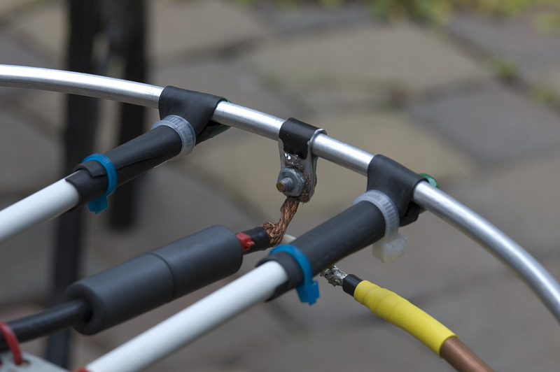
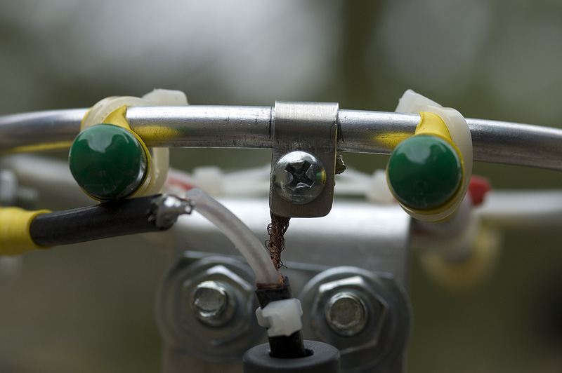
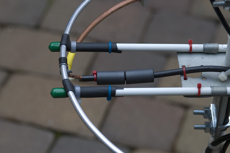
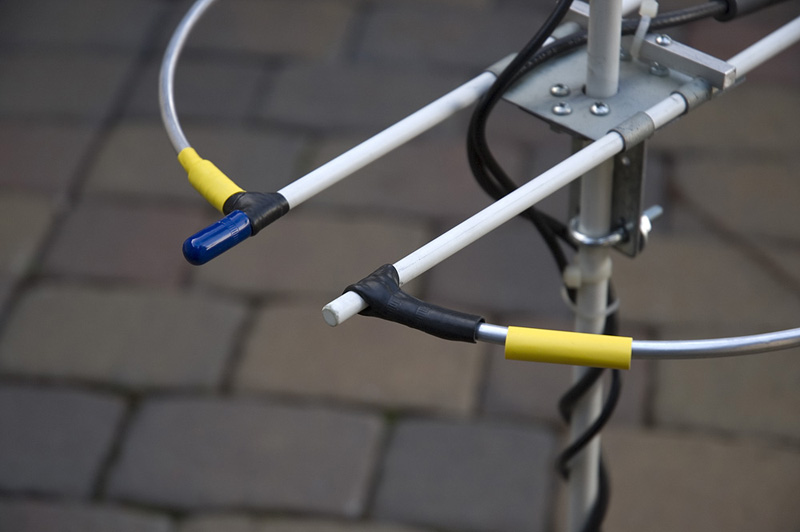
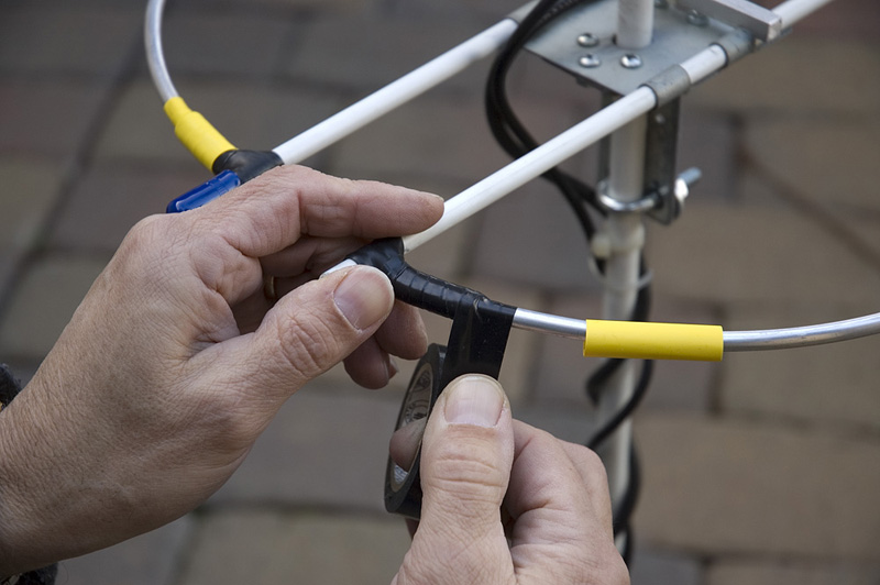
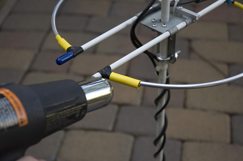
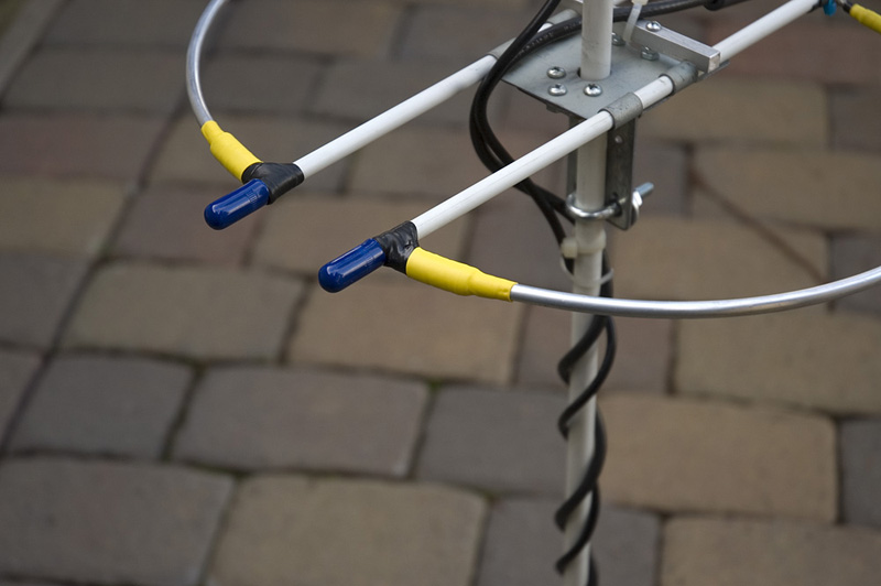
The picture on the left shows how the loop was attached on the closed side of the loop. I used this method to attach the 2 meter loop to the fiberglass rods during the debug and tuning stage and for several weeks thereafter. I was not satisfied with the way it looked. Also the durability of the plastic ties was in question. Even though the method of attaching the two meter loop was functional in that the materials used were insulators, I thought of a way to improve it. First I decided to use the same basic materials, but I modified how they would be used. The same coax insulation was used but this time it was attached to the loop with electrical tape rather than plastic ties. The tape was wrapped around the split coax insulation and then over the aluminum rod. The tape was wrapped so that is extended a small distance beyond the coax insulation. This would hold the aluminum rod in place. This assembly was then covered with heat shrink tubing to keep the weather from affecting the attachment. Below are pictures showing the steps involved. The image on the right shows the completed job.
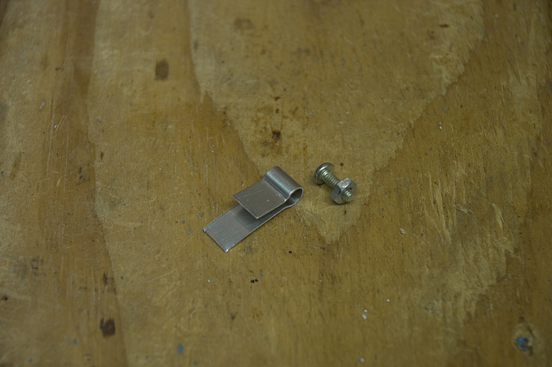
(Loop ground point connection bracket) 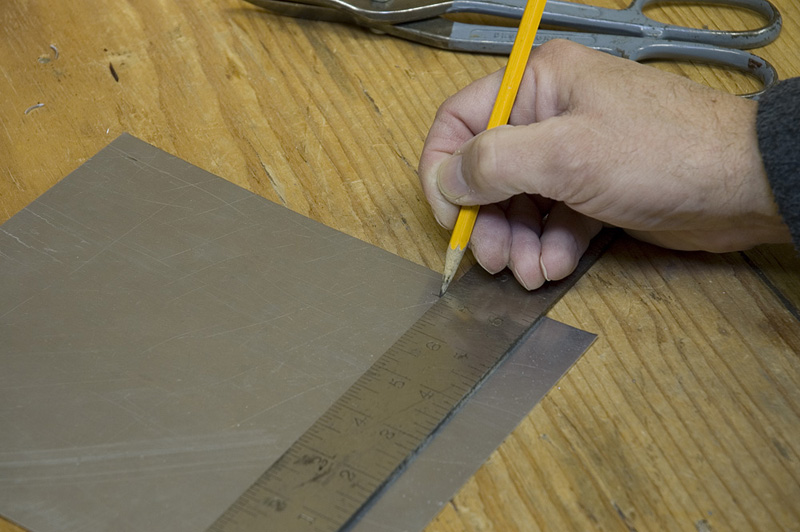 The straps used to connect the ground point of each of the loop antennas was made out
of flat sheet aluminum. A strip 1/2 inch wide was cut off of the sheet to fabricate
the brackets.
The straps used to connect the ground point of each of the loop antennas was made out
of flat sheet aluminum. A strip 1/2 inch wide was cut off of the sheet to fabricate
the brackets.
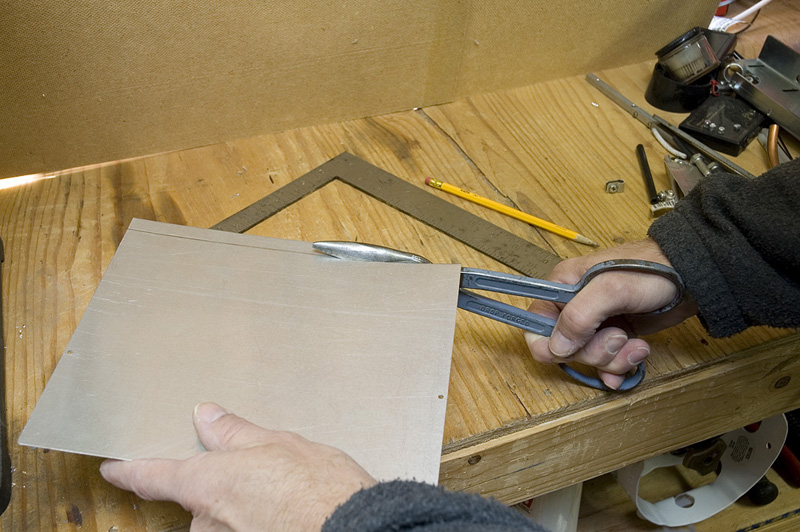 The material used was fairly thin which made it easy to work with. When
cutting the strip it will tend to curl.
You will need to flatten the aluminum back out which you may be able to do by hand.
If the material is too tough for you to flatten out by hand you may need to hammer it
flat on an anvil.
The material used was fairly thin which made it easy to work with. When
cutting the strip it will tend to curl.
You will need to flatten the aluminum back out which you may be able to do by hand.
If the material is too tough for you to flatten out by hand you may need to hammer it
flat on an anvil.
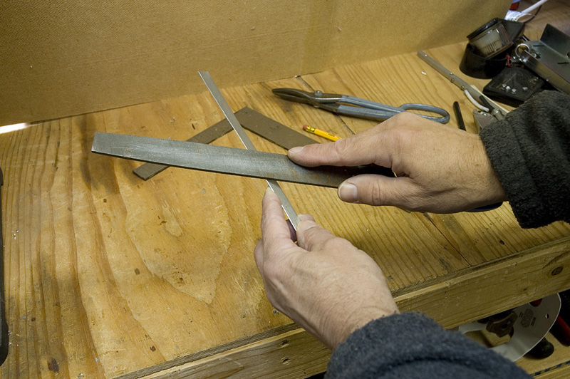
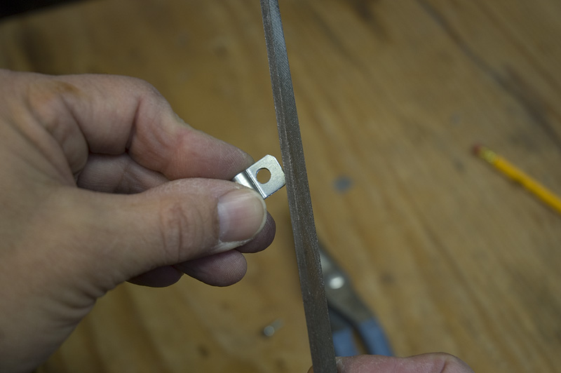
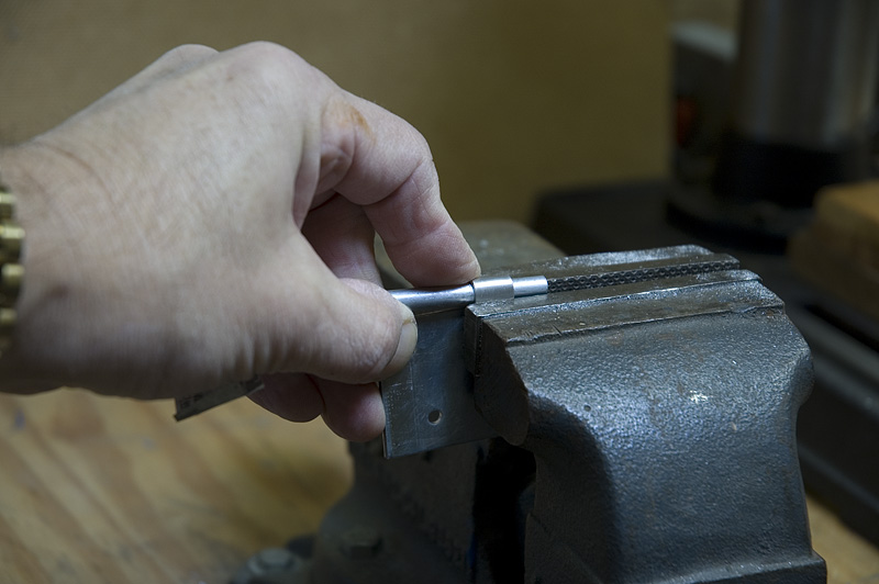
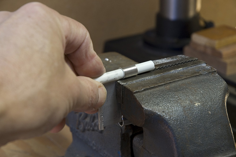
Once you have flattened the strip of metal back out it is a good idea to ease the edges
due to the sharp edges caused by cutting the material. I do this by just using a
metal file as shown in the picture to the left.
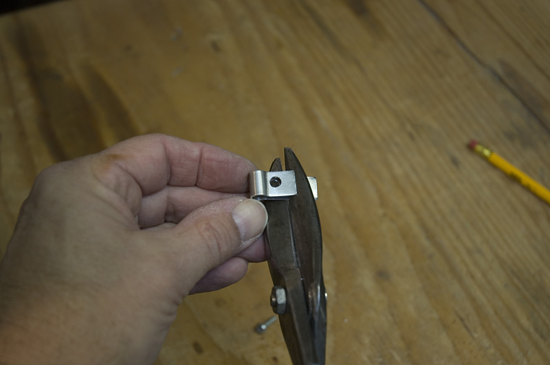
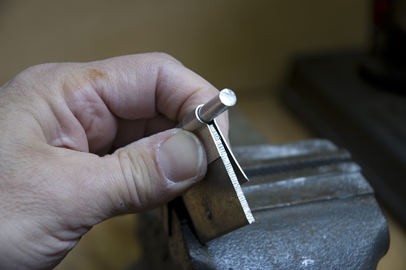
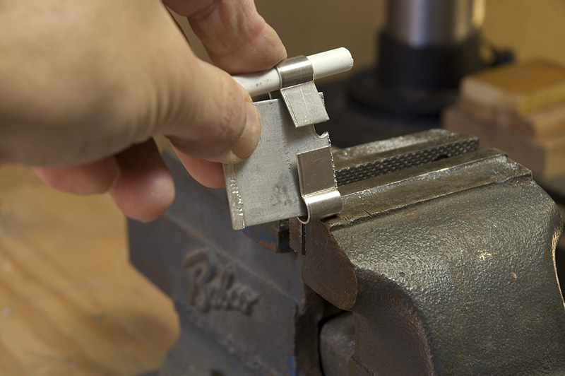
The series of photos below shows how the strip of aluminum is shaped to form the ground connection bracket. First start by bending the strip around the aluminum rod to obtain the correct radius. Note: if the material is thicker, you may need to clamp the strip to the rod before bending. This may be needed to keep the bend radius the same as the rod it is being bent around. The first picture shows the strip being bent around a piece of extra rod that was in excess of what was needed to make the 2 meter loop. It is a good idea to hold on to the scraps of material as you work your way through the project so that you have pieces for fabrication jigs if needed. The second picture shows a piece of scrap that will be used when crimping the bracket in the vice.
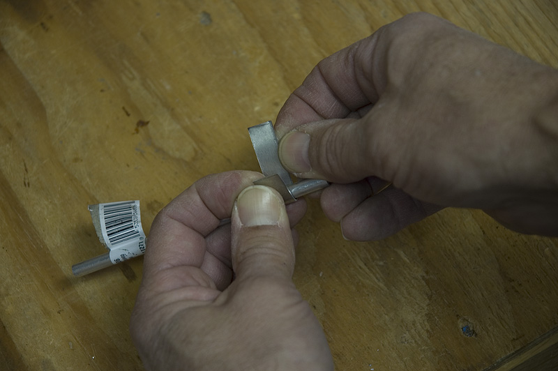
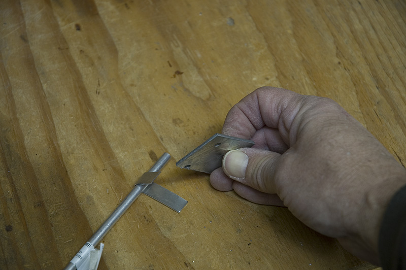
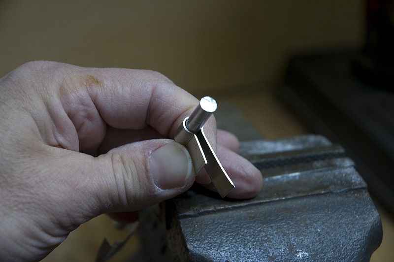
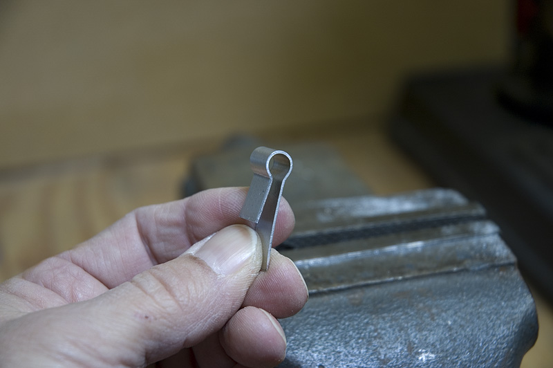
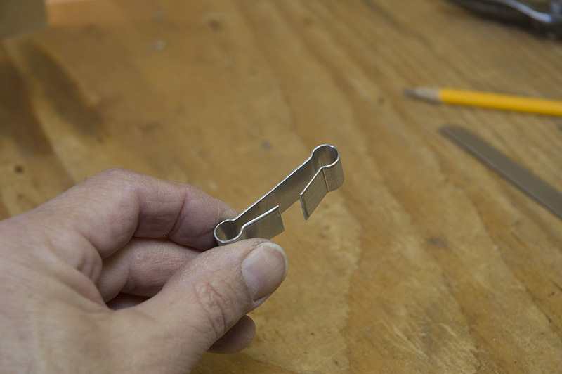
The third picture shows the bracket loop being formed around the aluminum rod in the vice. Note that the extra scrap of thicker material is being held between the two ends of the strip while it is being crimped. This will keep the loop from completing a circle around the rod thus providing some travel distance between the two ends when clamping it around the antenna rod. The fourth picture shows the completed bend around the rod while the spacer scrap is still in place between the two ends. The fifth picture shows the completed loop around the rod to show the profile of the completed clamp loop.
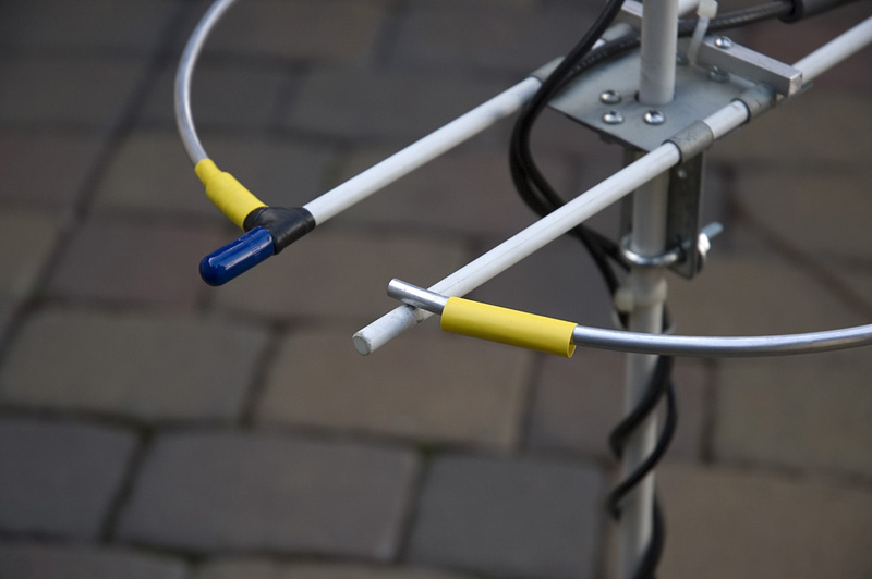
(Gamma match connection brackets) 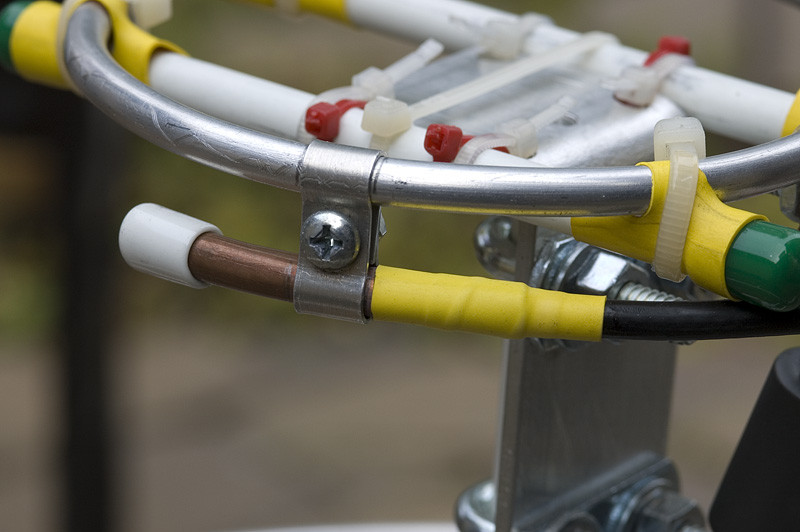 I used two different gamma bracket types for the two different loops. There really
is no reason for two different types, I just made them that way. Either type could
be used for both loops. For the 70cm loop I used a bracket that was fabricated out
of sheet aluminum the same way as the ground point brackets were made. The
same fabrication techniques can be used. The only difference between the ground
point bracket is that the gamma bracket has two connection loops that are opposite
one another with the screw point in the middle. See the picture to the left.
I used two different gamma bracket types for the two different loops. There really
is no reason for two different types, I just made them that way. Either type could
be used for both loops. For the 70cm loop I used a bracket that was fabricated out
of sheet aluminum the same way as the ground point brackets were made. The
same fabrication techniques can be used. The only difference between the ground
point bracket is that the gamma bracket has two connection loops that are opposite
one another with the screw point in the middle. See the picture to the left.
The 2m gamma bracket was made out of two pieces of 1/4 inch aluminum bar stock.
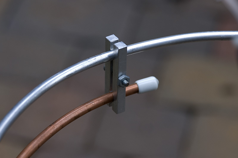
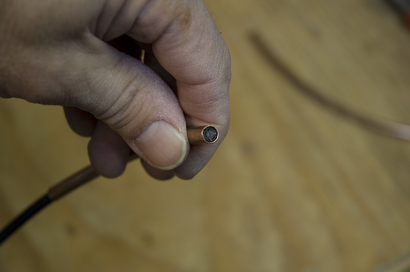
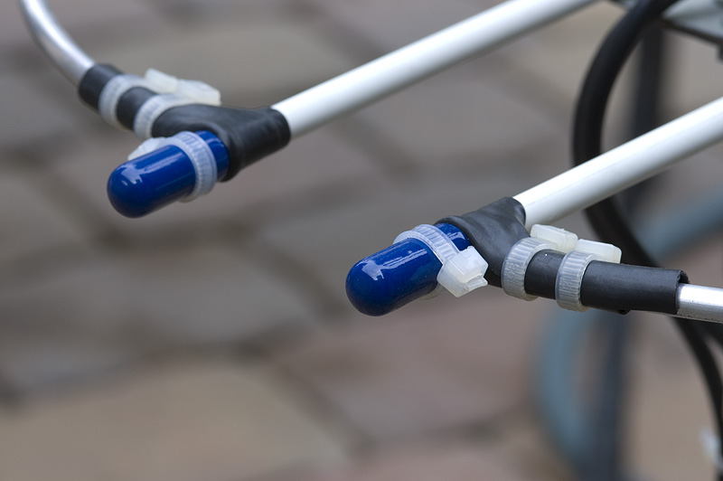
(Gamma match construction and mounting) 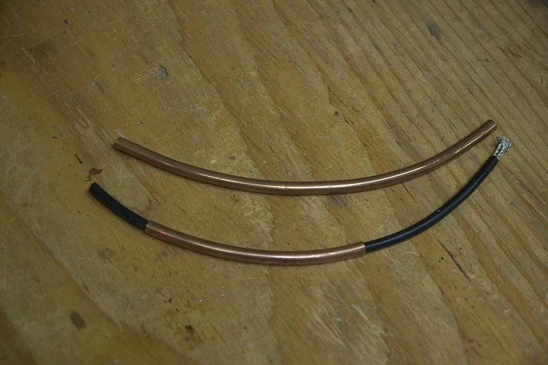 Both the 2m and 70cm gamma match tubes were made using 1/4 inch copper tubing. The
goal here is to build a variable capacitor that can be connected at a position on
the radiating element to obtain a 50 ohm match. You are also trying to connect to
the loop in such a way as to have the least amount of reactance as possible. This is
done by adjusting the gamma capacitive reactance until it cancels out the inductive
reactance. I have read that the amount of capacitance needed to accomplish this is
about 7pf per meter of wavelength but have found that this value varies depending
on antenna design.
Both the 2m and 70cm gamma match tubes were made using 1/4 inch copper tubing. The
goal here is to build a variable capacitor that can be connected at a position on
the radiating element to obtain a 50 ohm match. You are also trying to connect to
the loop in such a way as to have the least amount of reactance as possible. This is
done by adjusting the gamma capacitive reactance until it cancels out the inductive
reactance. I have read that the amount of capacitance needed to accomplish this is
about 7pf per meter of wavelength but have found that this value varies depending
on antenna design.
I found the RG58 coax fits nicely inside the copper tube. I connect to the coax
shield rather than the center conductor.
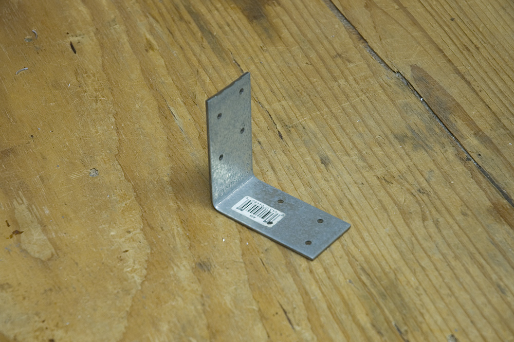
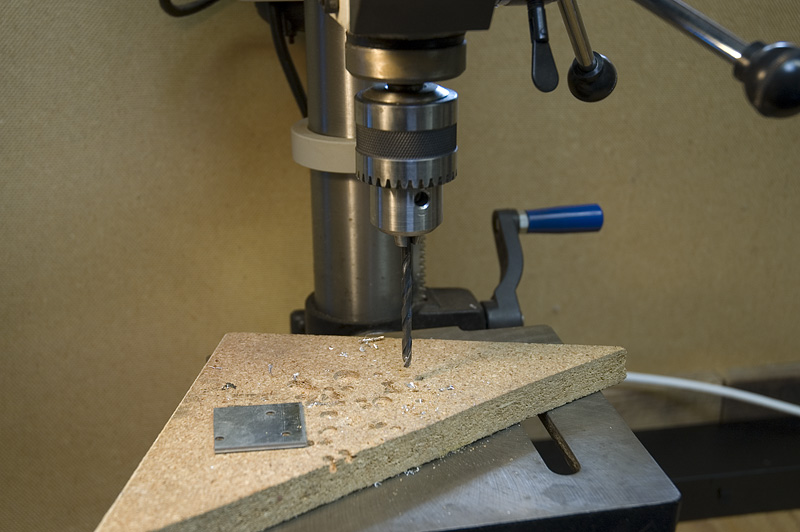
(Mast bracket for 70 centimeter loop) 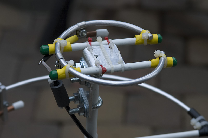 The 70cm mast bracket was made from the same angle brackets purchased at Home
Depot as shown at the beginning of this article. The top leg of the bracket was cut
down in length since it was longer than desired. Holes were drilled on the long
leg of the angle bracket for the U-bolts that attach the bracket to the mast.
Four holes were also drilled on the top leg so that the plastic ties could be
used to attach to the fiberglass cross rods. A picture of this original set up
can be seen to the left.
The 70cm mast bracket was made from the same angle brackets purchased at Home
Depot as shown at the beginning of this article. The top leg of the bracket was cut
down in length since it was longer than desired. Holes were drilled on the long
leg of the angle bracket for the U-bolts that attach the bracket to the mast.
Four holes were also drilled on the top leg so that the plastic ties could be
used to attach to the fiberglass cross rods. A picture of this original set up
can be seen to the left.
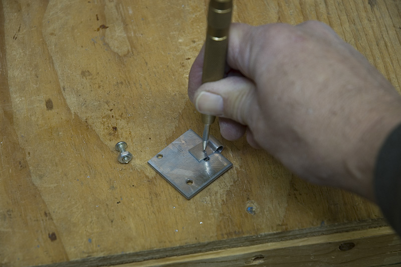
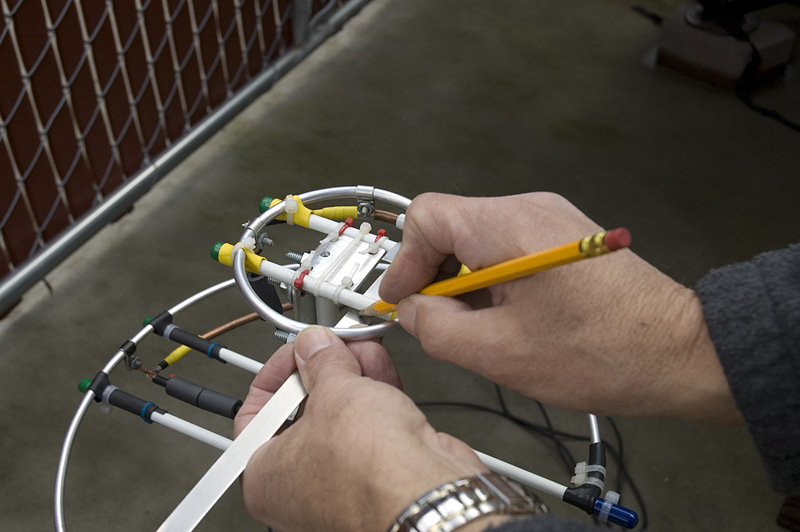
In the three images below, the first picture on the left shows a strip of aluminum
bent around one of the fiberglass rods. The second image in the middle shows
me marking where the edge of the second bend will be made. The third image on
the right shows the strip of aluminum after the second bend was made as I was
checking it for fit.
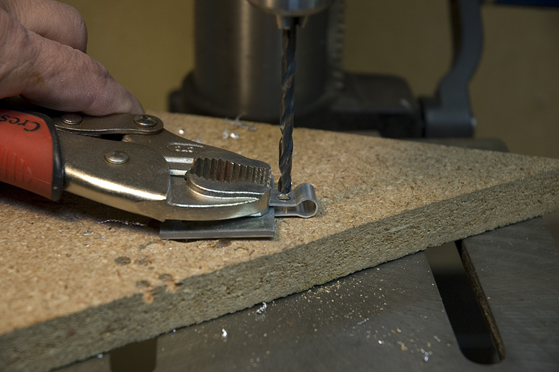
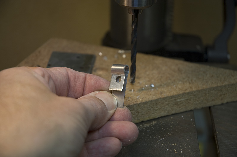
In this next set of pictures I show how the bent strip of aluminum is crimped to
fit as clamps around the fiberglass rods. The first picture on the left shows one
of the brackets being crimped. Notice that I have used a piece of scrap material
between the bracket so that there is still space left for the bracket to have a
clamping action around the fiberglass rod once the crimping is completed. The
second picture in the center shows one of the brackets after the crimping has
been completed with the scrap piece of aluminum still in place. The third picture
on the right shows the bracket that is almost complete. All that is needed is to
drill the holes for the mounting screws to go through and file off any rough edges.
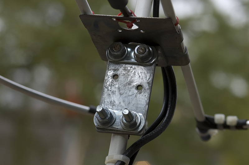
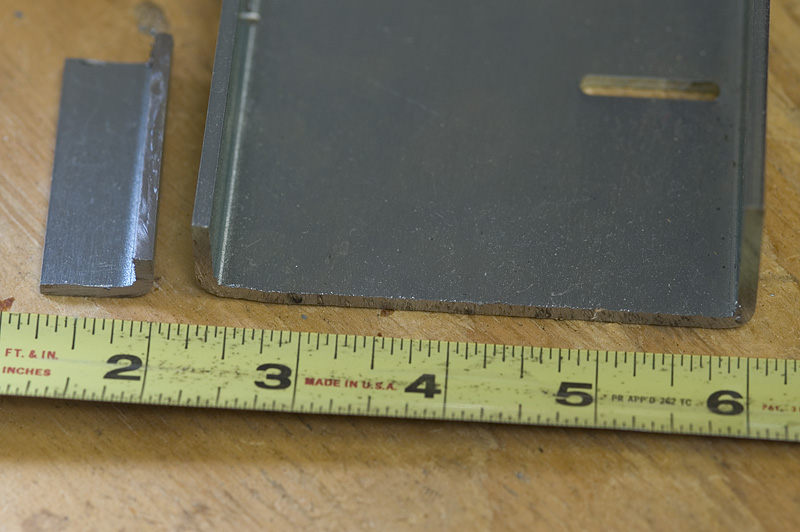
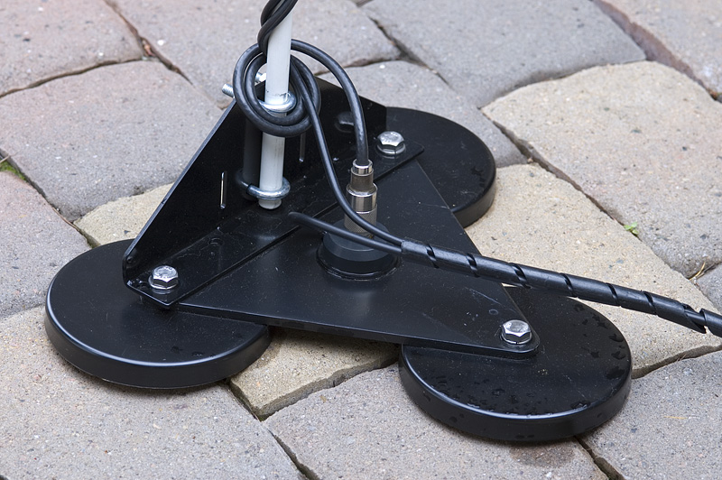
(Base mast bracket and magnet mount) The following pictures have been shown previously in this article but I wanted to show them once more to clarify how the mast is connected to the magnet mount. Originally I made a base bracket out of one of the angle brackets purchased from Home Depot. The only modification that was needed was to drill four holes for the U-bolts to fit through and one hole to attach it to the magnet mount. After a few days of driving I found that the mast was starting to bend back from the wind load. At that point I added the wire rods to keep it from bending. The rods are just a piece of coat hanger. The picture below on the left shows the original bracket once modified with the wire rods. The bracket was still a little weaker than I liked so I looked around for a studier solution. I found a heavier piece of steel that would work but it also needed to be modified. I cut it to shape using a hack saw. Once cut to shape and drilled to accept the U-bolts and magnet mount bolts I painted it to keep it from rusting. A piece of the raw steel used to make the stronger bracket can be seen in the center picture.
The last picture on the right shows the completed stronger bracket attached to the
magnet mount ready for use. The magnet mount was purchased from a local radio shop.
Tuning for resonance A couple of things should be noted before we go into how the antenna is tuned. First, any change made in the design will have an effect. Sometimes the effect can be much more than you would expect. I have a saying that emphasizes this thinking. The saying is "Everything affects everything else". So keep this in mind as you go through the tuning process. You may move the location of a component or change how something is made which in turn could change how the antenna operates.
Some of the things I have done in the design of this antenna tend to minimize a
couple of effects I have encountered. One is sealing the gamma match tube. This
really helps to keep the operations of the antenna consistent in a wet environment.
Tuning for resonance is simple but takes time. I built the 2m antenna first and added the 70cm antenna later. Once one of the antennas was fully assembled I used an SWR meter to determine if it was close to resonance at the desired frequency and if it wasn't I determined if it was high or low in frequency. I adjusted the position of the gamma tube connector along the antenna loop for best match. I also adjusted the wire inside the gamma tube for best match. I did this several times and determined that the resonant frequency was too low. This indicated that the loop was too long. I trimmed the loop down a small amount and tried it again. After adjusting back a forth several times I was able to get the SWR down to below 1.1:1. After everything was adjusted and I was satisfied with the SWR readings, I locked the wire in the gamma tube in place by wrapping a few turns of electrical tape across the end of the tube and wire. I then added heat shrink tubing over it to keep it in place. Conclusions
I have found that the antenna works very well. There is not much activity on
70 centimeters but there is a local group on 2 meters. I have talked to quite
a few contacts with good reports. I have not yet driven in all weather
conditions to know if there are any unforeseen problems. I have driven in the
rain without any detuning problems seen. There are two things that may be
issues. First is that the 70cm loop is attached to the fiberglass cross rods
with heat shrink tubing and plastic ties. I would like to improve on this
method. The other is that the mast which is 1/2 inch fiberglass rod does
wobble slightly as you drive over bumps in the road. The movement is minimal
and I don't think this will be a real problem, but it is too soon to be absolutely
sure.
© Michael Fedler, 2009 |
 As long as I was at it, I thought it would be a good idea to
build a second loop for 70 centimeters. I set out with the goal to build
the antennas out of materials I had laying around or materials that were
easy to obtain from the local hardware store.
As long as I was at it, I thought it would be a good idea to
build a second loop for 70 centimeters. I set out with the goal to build
the antennas out of materials I had laying around or materials that were
easy to obtain from the local hardware store.